Field Season is upon us! Plan ahead and double-check lead times before ordering.
A common question that people send to Jeff and me as the support staff at Wildlife Acoustics deals with how people should adjust their recorder settings. In particular, how to set gain. For example, "I'm trying to record X Species in Y Environment. How should I set the gain on my recorder?"
The documentation for our equipment provides some suggested starting points, but I always tell customers they should test out their settings and make adjustments if necessary.
So, how do you know if adjustments are necessary?
Setting the proper gain means understanding a little bit about what gain is and where it takes place in the recorder's signal chain - the path from sound hitting the microphone to a digital file stored on an SD card.
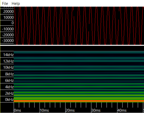
Clipped Sine
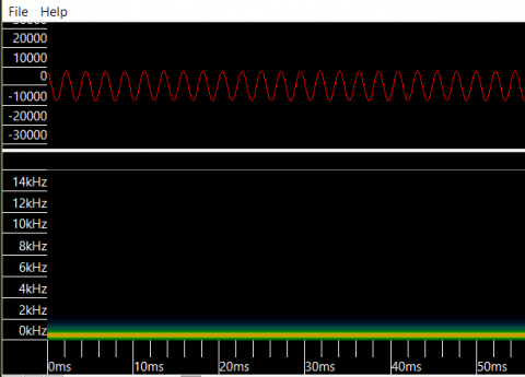
Clean Sine
When sound hits a microphone element, it is translated into an electrical signal - small changes in a voltage level over time that imitate the changes in air pressure that make up a sound wave. Adding gain means taking this voltage signal and multiplying it by a fixed value. For example, you might start with a signal that swings from -10 millivolts to 10 millivolts, then add gain to get a signal that swings from -100 millivolts to 100 millivolts. You can think of gain as making a signal louder.
In this next image, I have increased the gain on the sine wave until it has exceeded the range of the ADC. You can tell this is the case because the whole shape of the sine wave does not fit into the waveform view. It is instead chopped off at the top and bottom. Notice that instead of a single frequency being shown in the spectrogram, we see a lot of higher frequency content. By flattening the peaks and valleys of my sine wave, I have changed the shape of the waveform, and added a bunch of frequency content that wasnât there in the first place. (Why this happens is a topic for another day!)
So, if you notice that your recordings are frequently being âchopped off, this means that the signal hitting the ADC is too loud, and the recorder is unable to accurately capture the full shape of your sounds. To remedy this, simply try lowering the gain.
Join our mailing list to get notified about upcoming training opportunities, live webinars, quarterly grant offerings, product releases, and more.
Thank you for signing up to our mailing list.
You can unsubscribe or change your email settings at any time by clicking "Manage Preferences" link at the bottom of any mailing list emails we send you.